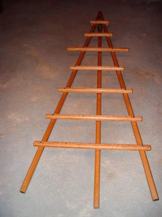
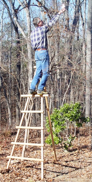
 Figure 1 – Red oak tripod ladder
“Thanks to Masanori Yamakami for sharing his knowledge of Japanese craftsmanship and gardening. For this class, Yama-san had several sizes of ladders he had constructed from hickory saplings, primarily with Japanese hand tools. He mentioned that it might make sense to construct ladders of this design from milled lumber such as oak. This was a result of our discussion of the difficulty of locating, seasoning or aging, and working with the different sizes and shapes of saplings. One would be inclined to use what they had rather than make another trip in search of the perfect sapling and wait a year for it to dry.
What follows is a description of a 10′ ladder that I built from red oak lumber using Yama’s design concept (as best as I could remember). I have used the ladder several times and it works very well, especially for pruning trees that are too small to support an extension ladder. I have included the reasoning behind the design and fabrication techniques as I understand them.
I appreciate Yama’s collaboration and knowledge to allow me to build this useful tool and to share it with others.” – Steve Burkhalter, 2009.
DESIGN AND CONSTRUCTION
Objectives: A few important things a ladder must be able to do:
- be a safe and steady working platform for people to perform pruning, picking or related tasks above the ground level.
- be self supporting so as to access the outer portion of tree limbs and not damage the tree by resting on it.
- be easily moved and set up by one person.
- be stable on a variety of slopes in any direction.
- not damage small shrubs or flowers at the base where it is used.
Dimensions: The height should be 2.5 to 3 times the width at the bottom for a balance between stability and height/space/weight considerations. The maximum height of working access of a person on the ladder is approximately 3.5′ above the ladder length.
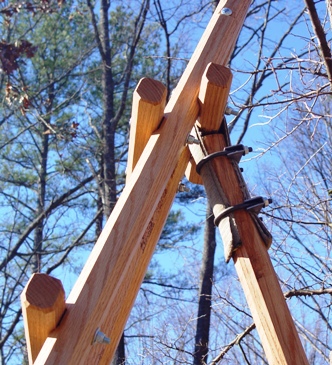
General Design: The ladder is basically a tripod with horizontal steps joining two sides (Figure 1). The third leg of the tripod is movable about a hinge joint that allows both front to back and limited side to side motion (Figure 8). This limited, side to side motion gives stability on side slopes – a major advantage over virtually all manufactured ladders. Here are some details:
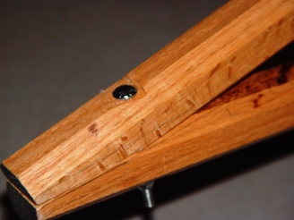
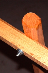
- The support legs and rungs are constructed of wood and fastened using bolts and nuts. I used 5/16″ carriage bolts with nylock nuts and washers.
- The holes for the bolts should be drilled 1/32″ or 1/16″ oversize for clearance and to accommodate any twisting and misalignment. Try to minimize the extra clearance diameter so the square portion of the carriage bolt head grips to make tightening of the nylock nuts easier.
- The wood used must be strong enough to support an individual’s weight as well as the tools he may be carrying.
- The rungs should not be slippery or have an unstable coating.
- All components should be resistant to damage by weather.
Traditional Construction: Japanese tripod ladders were traditionally constructed from bamboo and tied with” MYKs” (Magic Yama Knots)! Yama-san has extraordinary knowledge of knots useful in the various aspects of gardening, especially Japanese gardening that requires training of plants and trees. The knots all seem simple and work incredibly well (like magic). I’m sure this comes from years, or centuries, of experience, but they are too hard to remember from one day’s exposure. Whatever you need to have a rope do, ask Yama-san.
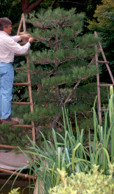 Figure 2 – Fat gardener on sapling ladder Figure 2 – Fat gardener on sapling ladder |
An alternative to bamboo is to construct ladders using saplings, which is what Yama demonstrated in the class. The best saplings are hickory (strong and tough wood) and must be quite straight and the proper diameter – a difficult commodity to find. You have to find them, then obtain permission to harvest them.
- The vertical supports on an 8-10′ ladder would use saplings of 2.5 or more inches in diameter at the bottom and 1.75 or more inches at the top.
- The horizontal rungs can be a little smaller, at 1.5 to 2 inches for the bottom rungs and 1 to 1.5 inches for the upper rungs.
This very much depends on the weight of the user. I believe these figures are good for about 180 lbs. Of course, standing near the connection points is much stronger than center span. You do get a fair amount of flex in the rungs which is why toughness of the wood is as important as strength.
Saplings may have inconsistencies which could lead to failure (See Figure 2). They also need to be roughened after the bark falls off (or is removed). Since sapling diameters are not equal for the entire length, be sure to make the mounting edge level when mounting the rungs. Tulip poplar is another possibility because it grows fast, straight, lightweight and is plentiful. However, it is quite soft and lacks the strength of the hardwoods.
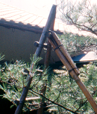 Figure 3 – bamboo hinge Figure 3 – bamboo hinge |
The connection of the back support leg was traditionally made by splitting a bamboo pole lengthwise 180° apart a couple of feet from the end. The split area was heated and bent around a mandrel of the diameter equivalent to the back support rung. After the proper form is achieved, the back support is slipped over the back support rung and wrapped and tied back on itself with” MYKs”. The split part flattens out and forms a fitted sleeve around the mandrel (Figure 3). It looks really slick and allows the side to side motion required for side hill applications.
BUILDING A JAPANESE TRIPOD LADDER FROM LUMBER–
Determine the size desired: The maximum working height of access is about 3.5 feet higher than the height of the ladder or length of vertical supports. This is for an average height man and takes into account the 6 inch difference between the length of the vertical supports and the actual height due to the angles between the legs in a typical setup. The weight of the ladder is approximately 50 lbs. for the 10′ ladder I made.
Determine the spacing, location, and length of the steps:
- The lowest rung should be located about 18 inches from the ground to avoid damaging flowers and shrubs during setup, use and relocation.
- Locate the highest working level rung at your waist-height down from the top. This will allow you to rest safely and comfortably against the ladder (up to your waist) while working. I used about 40 inches.
- The rungs between the lowest and highest working level should be consistent and between 10 to 15 inches apart. Mine came out to 3 rungs about 15 inches apart.
- The two rungs above the highest working level and top of the ladder worked out to about 14 inches each. These would only be used as an access rather than a working platform unless there was another support available.
- All rungs should be long enough to extend beyond the vertical supports by enough to support a work shoe insole. I was comfortable with about 2.5 inches since I don’t expect to use the ends routinely.
- The highest working level rung should be longer than the others to provide additional access for work laterally. I extended the rungs about 8 inches past the vertical supports on each side. I could stand on that with both feet close together and it feels very good with one foot outside and one inside the verticals.
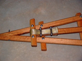
- Locate the rung that will be attached to the third tripod leg (back support) near the top of the ladder in an area that will not block you from putting your foot on the top front rungs and is not exactly aligned with any of the front rungs. As you will see below, I inset the rungs into the verticals about ¼ inch. I would not want to lose the cross section strength by cutting into them on the front and back at the same location. I spaced my back rung 2 to 3 inches above the top rung. If I were to build another, I would probably place it 2 to 3 inches below the top rung to avoid possible interference. So far, I have not had a problem. This back rung will be wrapped with sling material. You may want to adjust the location of the rung such that the clearance at the top is about ½ inch wider than available sling width. The sling material should be at least 2″ wide.